
Tinkercad Tutorial – Quickly get to a printable model
Tinkercad is a browser-based software that can be used to create more or less complex 3D printing models. The advantages are the usability without installation on all operating systems, the very easy handling and the clear menu navigation. In addition, the created models can be easily shared, for example directly to thingiverse or MyMiniFactory.
You will get to know the menu and the functions of the tool and then design a keychain, which you can then print with your 3D printer kit (LINK). You can print it out at home.
Registration on Tinkercad.com
To create and then print your own models, you first need an Autodesk account. This is free of charge.
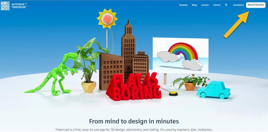
Click the Register button on the Tinkercad.com home page.
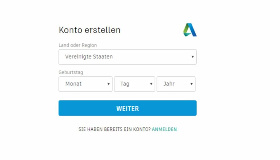
Then you select your country and enter your birthday.
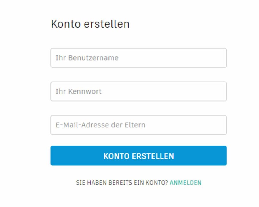
Now choose a username and a password that is not so easy to guess.
If you are under 13 years old, you will be asked to enter your parents' email address. This allows Tinkercad to notify your parents that you want to register there.
Now click on CREATE ACCOUNT
After the account has been confirmed, you can log in by clicking on “Log in”.
At the first login you can go through a tutorial of Tinkercad. But you can stop that at any time and rather continue here 😉
In the 3D Designs section, your 3D models are displayed. When creating models, Tinkercad generates custom names that you can edit during modeling or afterwards.
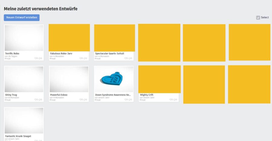
Now click on Create new design here.
The following workspace will appear. In the center is the work plane where you create and edit the model.
Around it are the following areas:
- Design name
- General functions
- View options
- Display options and editing capabilities
- Tools for selecting the work plane or ruler
- Model category selection
- Models of the respective model category
- Grid settings
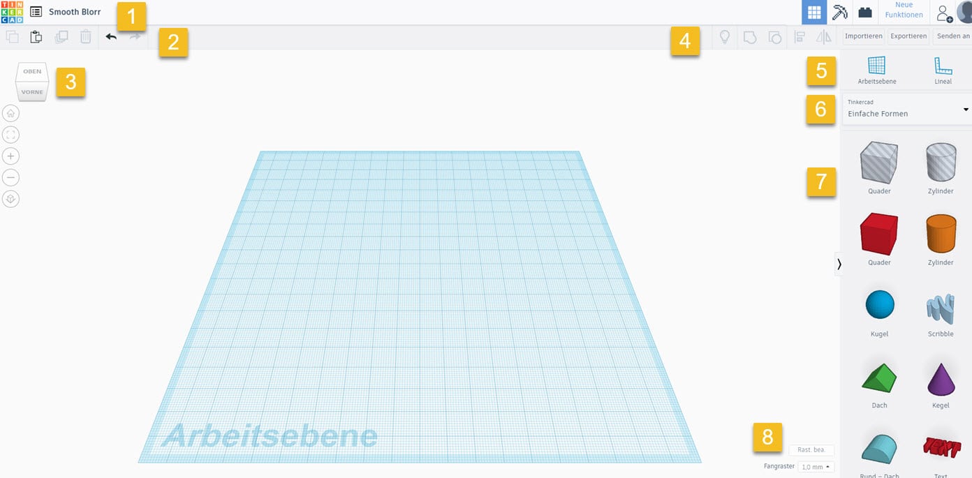
1 Name of the design
Here you can easily edit the name by clicking on it, here Smooth Blorr.
2 General functions
Here are the functions (from left to right)
- Copy
- Insert
- Duplicate
- Delete
- Undo
- Restore
to find. Undo lets you undo a step you've already taken with each click. With Restore you can virtually restore the undone.
3 view options
In this section you can find the options that allow you to change the view of the work plane. So you can click on all the corners, edges and named faces on the cube to change your point of view.
When you click on Top , you change the view to “View from top” and look at the work plane from above.
4 Display options and editing options
Tinkercad offers you the possibility to select the following options:
- Show all
- Group
- Ungroup
- Align
- Butts
and behind it directly
- Import (Here you can import 2D or 3D files in .stl, .obj. or .svg format)
- Export (3D printing: .obj and .stl; laser cutting: .svg)
- Send to (For example, directly to Autodesk Fusion 360 for further editing in a more professional tool).
5 Tools for selecting the work plane or ruler
You can use this to move the work plane. This means, for example, that you define the surface of a box as the zero point, so that all new objects are placed directly on it and do not have to be moved first. (Let's use below)
With the help of the ruler you can see if the objects you created are at the right distance from each other, or if you still need to make changes to them. If you want to create a table with Tinkercad, this way you can evenly distribute the table legs.
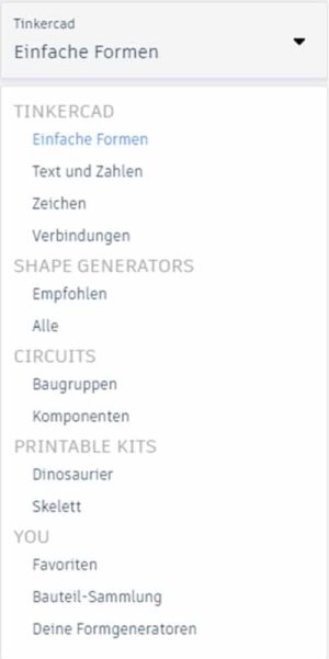
6 Model category selection
When you click on the field, the following menu will pop up and offer you a variety of categories or catalogs from which you can then select a shape or even entire models.
7 models of the respective model category
Once you have decided on a model category, the respective objects are displayed here. You can then simply drag them onto the work plane with the mouse.
8 grid settings
In the grid settings of Tinkercad you can define the size of the work plane and set the size of the snap grid. Thus, several 3D printers are already set. If yours is there, you can select it. The size of the work plane then adjusts accordingly. Otherwise you can enter the values yourself.
With the snap grid you virtually determine how far an object is moved when you use the mouse or arrow keys to move it. 1.00 mm is preset. Each time you click an arrow key, the selected object moves exactly one millimeter.
Edit shapes – What is possible?
Here I'll show you what settings you can make on a simple shape like the cuboid, so you can get a first idea of the possibilities.
First take a cuboid and place it on the work plane. After dropping, the box is selected and the properties of the shape appear on the right.

These vary from shape to shape, of course, but generally you have the option at the top to lock/unlock editing of the model or to hide the model.
Then you can choose whether the shape should be a solid or a hole.
Solids you will be able to see at the end. Holes are used only to pull them off the solids. By clicking on Solid you can change the color of the model. Of course, this will not change the color of your printout at home 😉
The radius is related to all corners and edges. If the switch is at the maximum value, the cuboid becomes a sphere.
Steps is worded a little confusingly. The lever actually only changes the resolution of the model. If you want a reasonably nice curve, you must select the maximum value here.
On the other hand, if you intentionally want to save your object as low poly, the lever should be more on the left.
You can also set length, width and height here, but that's more of a gimmick.
To make settings directly on the mold, let's take a closer look at it:
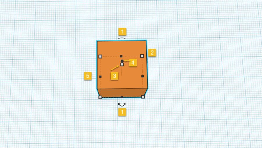
Different squares, circles and arrows are displayed on the shape depending on the viewing angle.
If you move the mouse over one of these objects, you will see the corresponding size information. You can now hold this point with the mouse and zoom in or out.
Tip: This is not necessarily always accurate, especially if, for example, you want one side to be 12.34 mm long instead of 12.30 mm.
To be able to enter the values yourself. Just click on the arrows at 1 below:
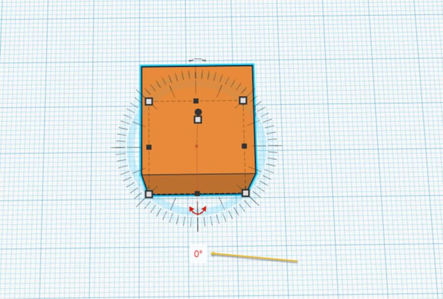
Then Tinkercad knows that you want to rotate the shape around its own axis. Click and change the value to 0° and see what happens when you change the value to 45° or 120°.
This way you can change all lengths and angles in Tinkercad.
If you click on the 2, you will see the following picture:
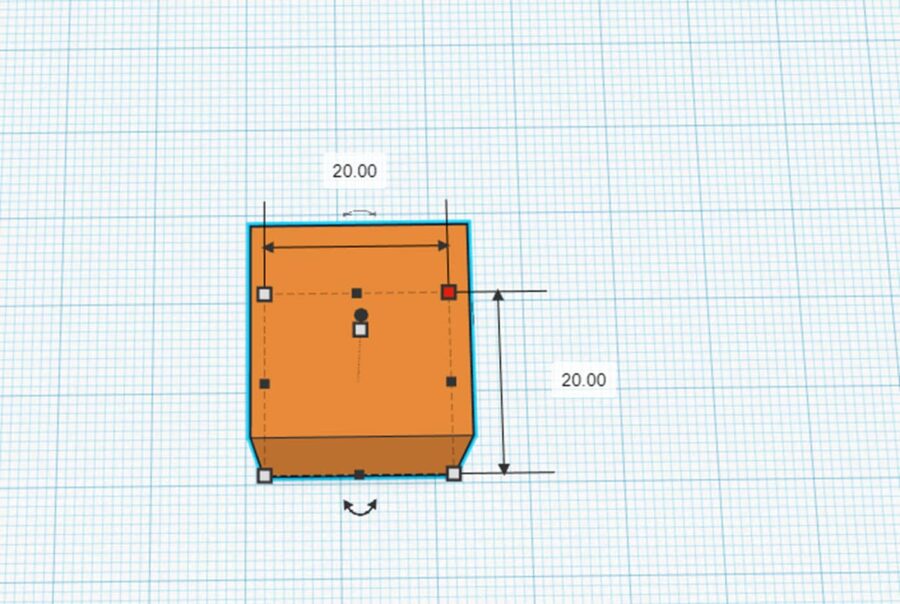
Here you can now change the lengths of the sides that cross at this point. Click again on one of the values, insert a new one.
Enter.
Ready!
Tinkercad always shows you to which side or axis (for angles) the respective function refers.
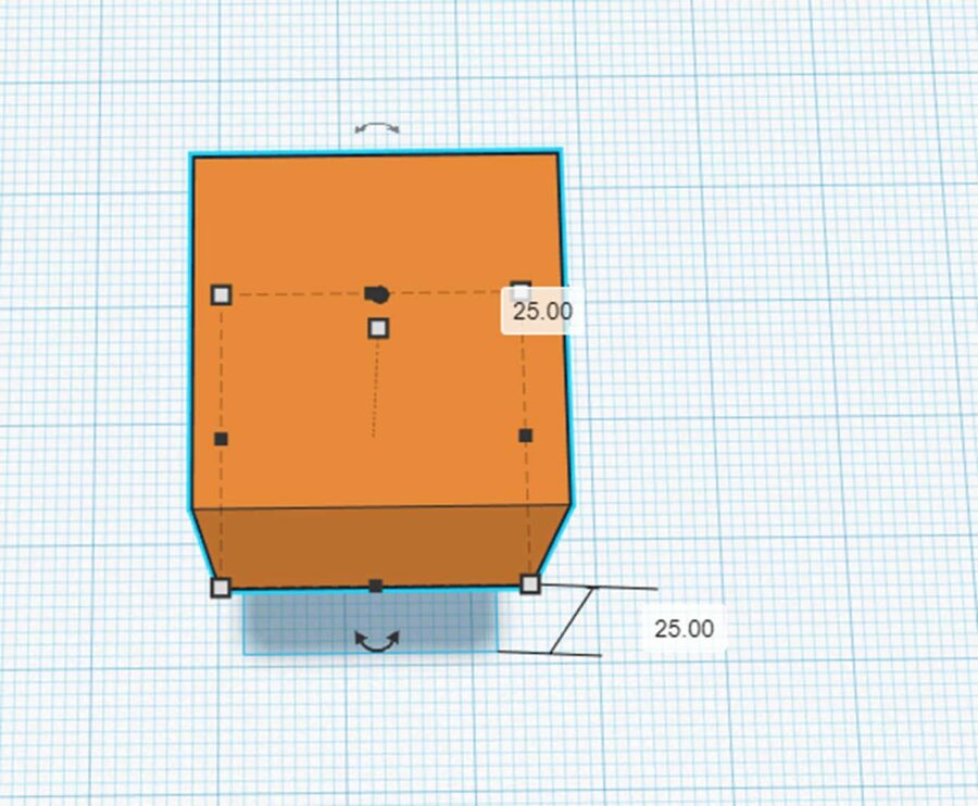
Change position
To change the position of the box, it is sufficient for the X and Y planes to select the box and move it with the arrow keys or the mouse itself.
To move the box upwards – away from the work plane – you must grab the point 4 shown above with the mouse and move it up or down.
Here the Tinkercad again shows how far you are from the work plane.
If you now drop the shape, you will see the distance (25.00) again with the possibility to enter it yourself:
Now you know your workspace and how to edit a shape.
Now we come to the modeling!
Model keychain with Tinkercad
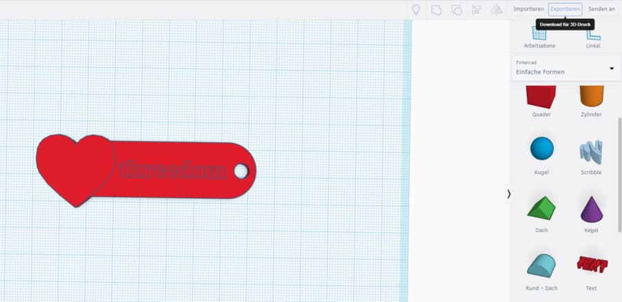
With this tutorial you will learn how to model the following keychain:
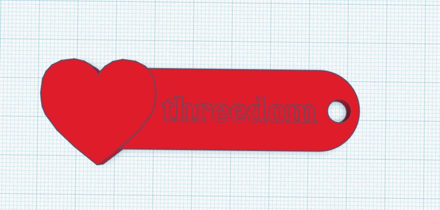
Of course you are allowed to use another font than threedom 😉
Step 1: Install and edit cuboids
For the first step, take a cuboid and place it on the work plane.
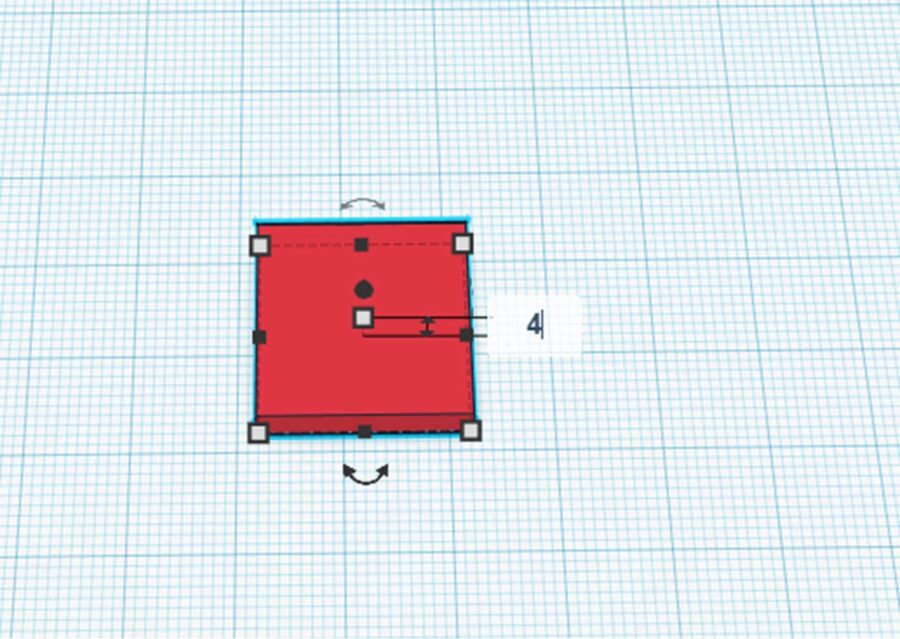
By clicking on the upper square you can change the height of the box.
Choose 4 mm here.
Then we want to edit the page lengths.
By clicking on the square at the bottom right, Tinkercad will show you that you can now change the side lengths:
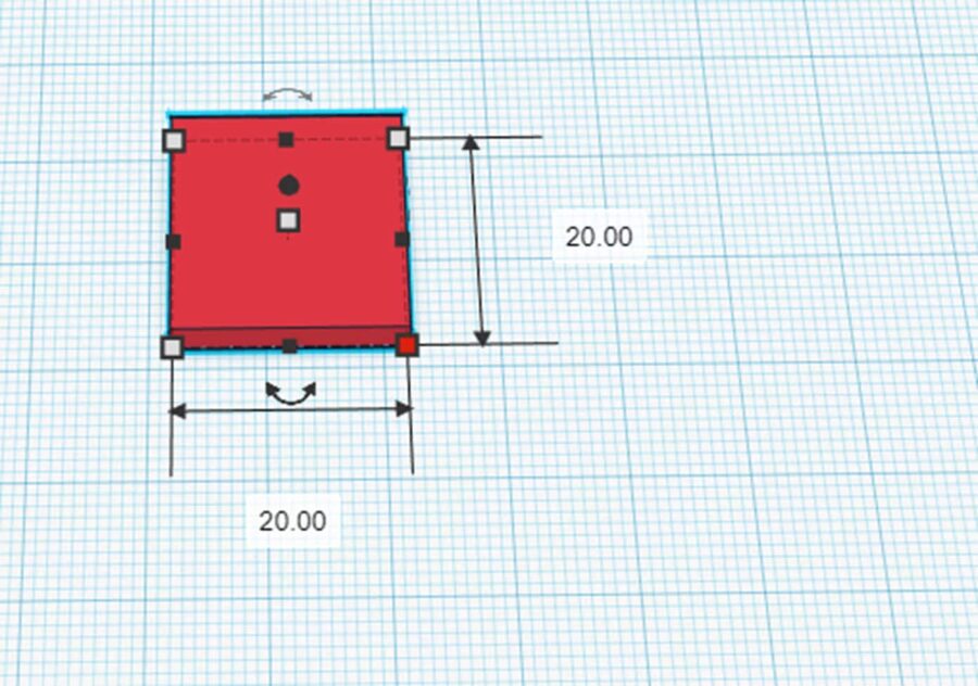
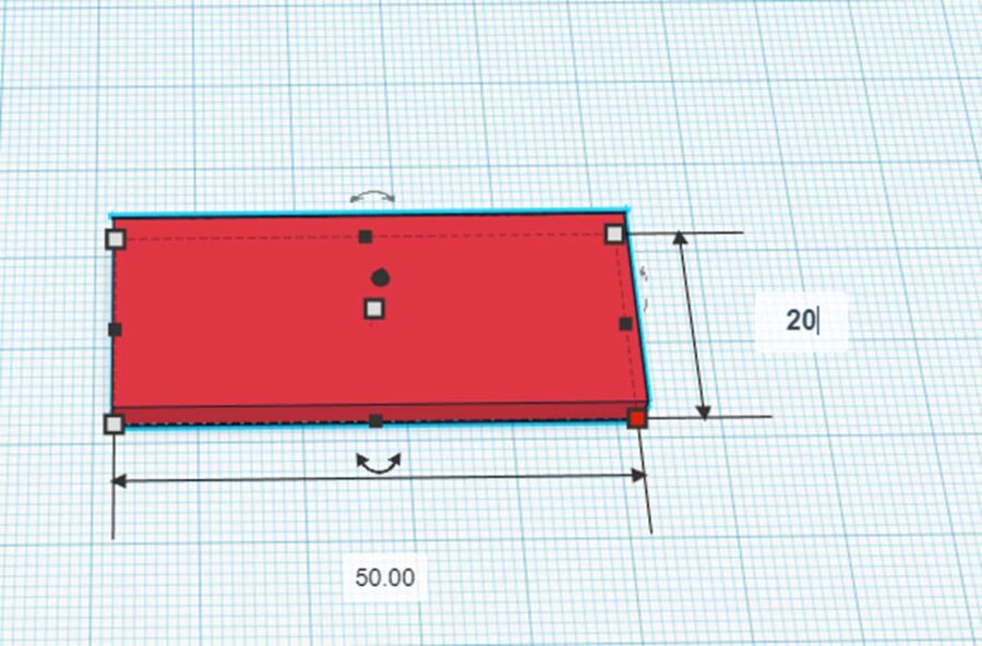
Here you take 50 mm for the length of the keychain.
The width of 20 mm is not too wide and not too thin. Therefore, we leave this value as it is:
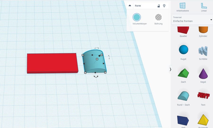
Step 2: Install and edit round roof
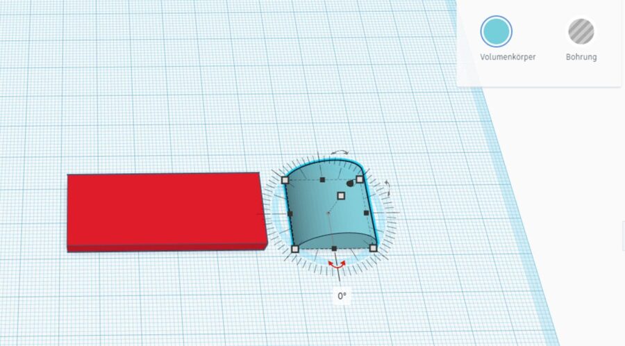
Then take the Round Roof shape and place it on the work plane as in the following picture:
We now turn this shape twice so that it stands the way we want it to.
To do this, click on the lower double arrow and the angle function will appear. Click on 0° to be able to change the value.
Select 90° here:
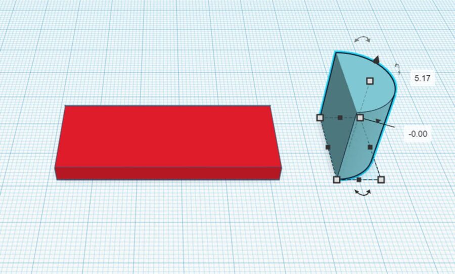
Now the form round-roof still need to turn upwards.
Click the double arrow icon and click 0° again.
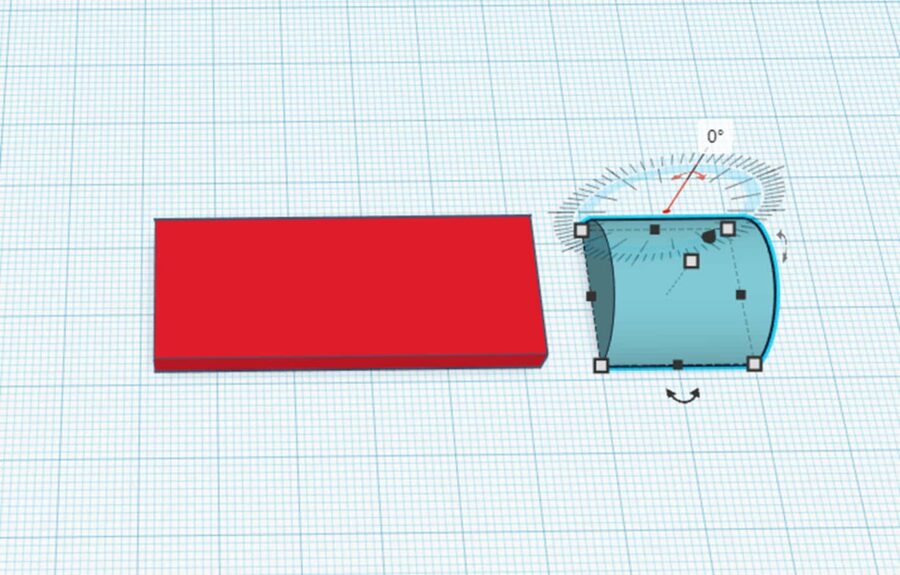
Here you now enter -90°.
This almost looks right….
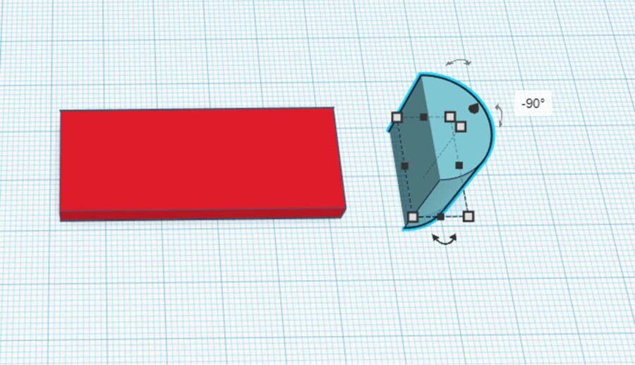
…but only almost. The mold now lies with a part below the working plane. To fix the problem, hold the arrow pointing up with the mouse and move it up as long…
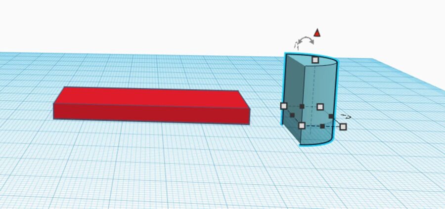
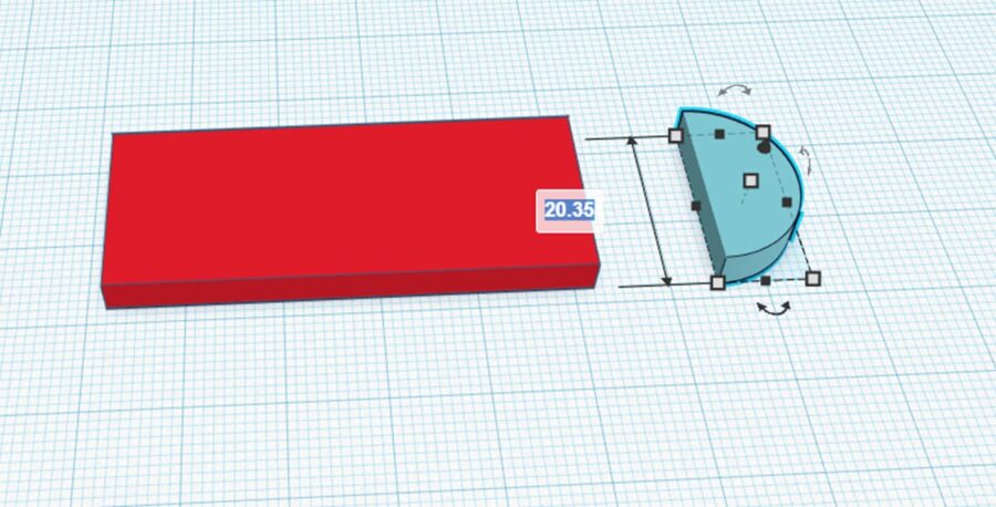
…until the value +/- 0.00 is reached:
Look at the side length of the shape. For me, the value has changed to 20.35. I change this back to 20.00.
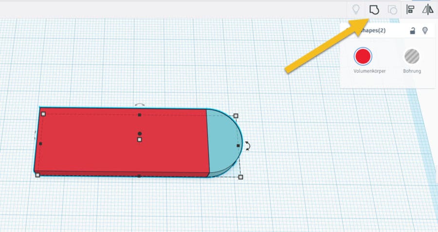
Now select both parts on the work plane. This is what happens:
- Ctrl+A – Selects everything (we have only 2 objects and we want to select both of them. Therefore no problem)
- You can select both with the mouse just as you would select text in Word.
- Press the Shift key (The one above Ctrl) – Hold it down and click both objects one after the other. Now both are marked.
Now click on Group so that both objects are merged into one shape. With the button to the right of Ungroup you can remove a grouping.
Step 3: Drilling for the ring
Then drag the upper cylinder into the working plane.
The upper cylinder differs from the other only in the fact that bore is preselected in the setting. If you click on solid here, it becomes a solid again.
Similarly, you can make a bore out of the lower cylinder by clicking on Bore in its settings.
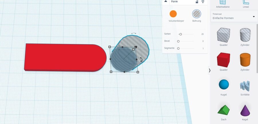
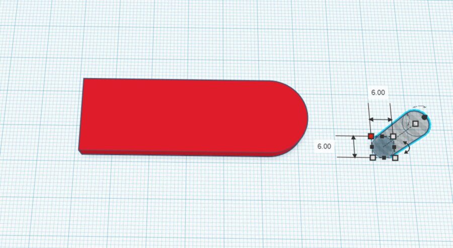
Now we change the values of the cylinder to 6 mm on both sides.
No radius or diameter is selected. So you can also create an ellipse if you like.
The height of the hole does not matter in this case and can be left as it is. The height of the hole here should be at least the height of the key fob (4 mm).
In order for the hole and the keychain to line up, you now need to align them.
Select Hole and Keychain – as described above – and then click Align.
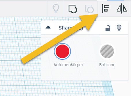
Now you can determine on which lines the two objects should be aligned to each other.
The center of the three right points aligns the centerline of the follower with that of the hole.
Feel free to test out the other points to get a feel for this feature.
It is very useful.
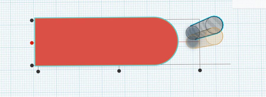
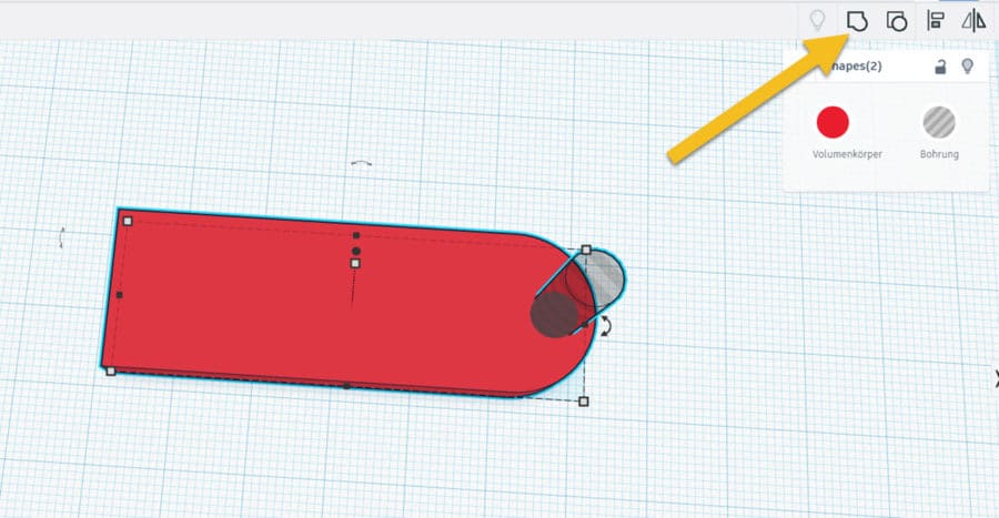
Now select both objects again and this time click on Group.
The hole is now removed from the solid.
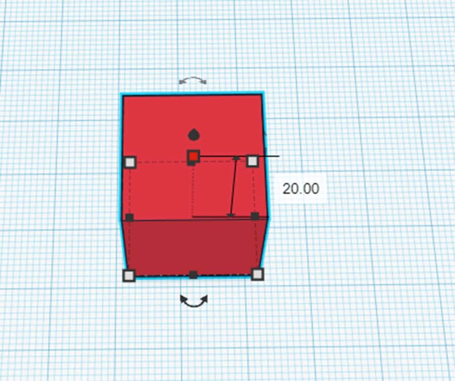
Step 4: Inserting a heart and the lettering
It is missing and still the heart and the lettering.
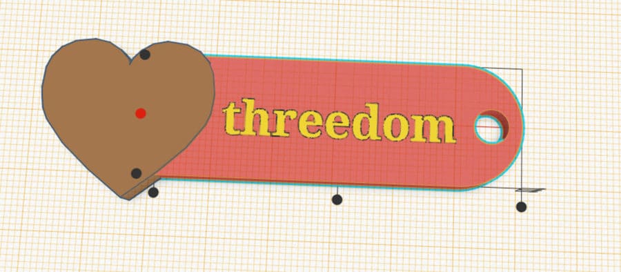
Now drag the heart to the working plane.
(Please don't ask me why the heart in particular got such a great color 😉 )
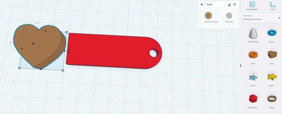
Here we change the height of the heart to 5 mm so that it peeks out a little from the keychain.
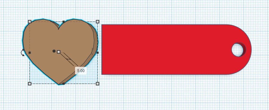
Move the heart so that the overall image looks something like the following picture.
Click on Work Layer at the top of the right page and move the mouse to the keychain.
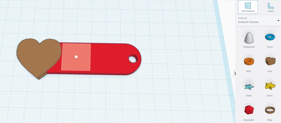
With one click, the surface of the keychain becomes the work plane and all new objects are placed directly on it.
This way, you don't have to drag each object to the top first.
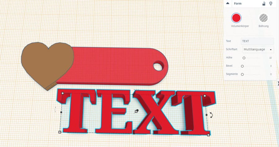
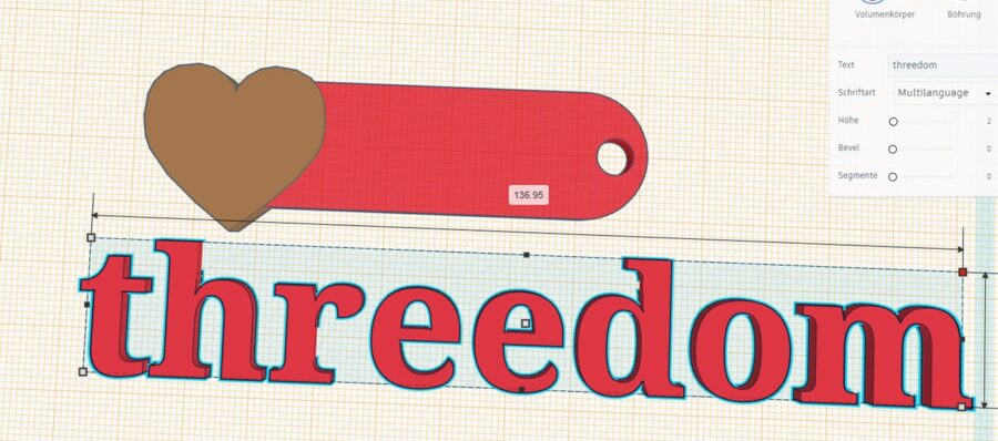
Then drag the Text shape onto the work plane. In the settings on the right you can change the text in it.
We take threedom here, of course 🙂
In the next step, use the mouse to select the box at the top right, for example.
Now hold down the Shift key (remember: that was the one above the Ctrl key) and use the mouse to drag the lettering to the desired size.
With the Shift key pressed, the font is reduced evenly. Without it, the lettering will be compressed.
Feel free to try this out.
You won't break anything in the process.
Then slide the lettering onto the keychain:
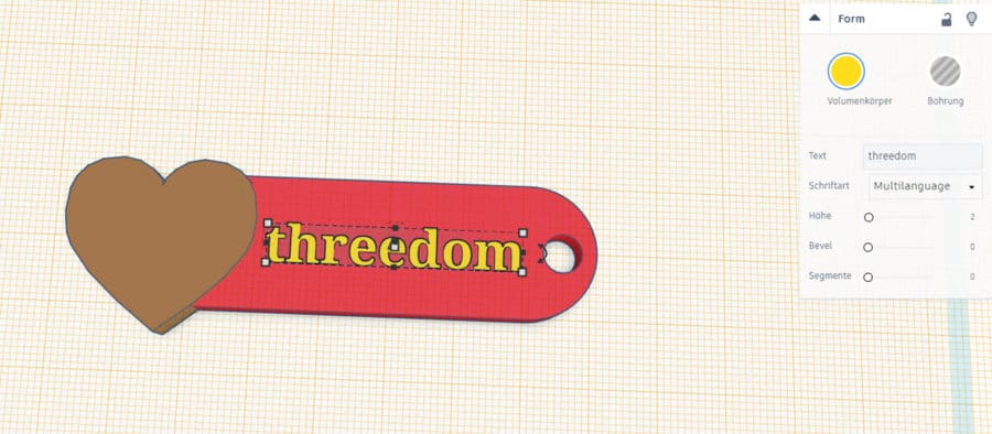
If you like, you can now mark the keyring and the lettering and then place the lettering in the center again by aligning .
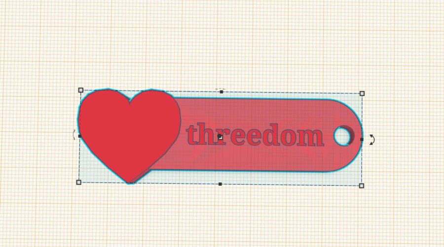
Last but not least Select all objects (keychain, heart and lettering) and click Group.
Your keychain is now ready!
You have become a true Tinkercad expert!
Step 5: Export
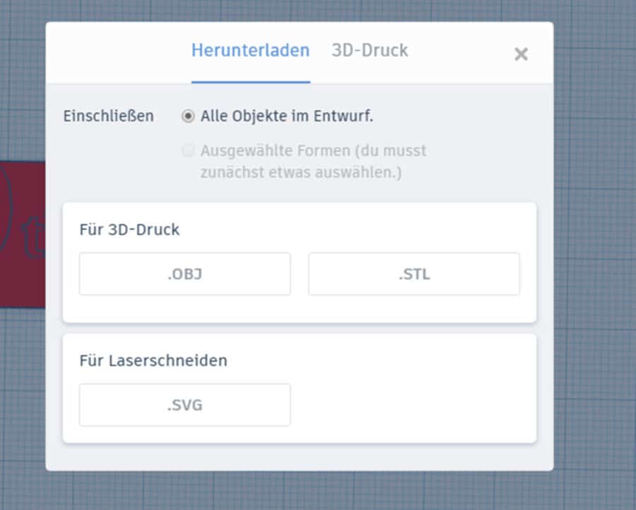
To do this, click Export.
Now you can download the file or send it to a compatible 3D printer or 3D printing service.
Since we want to print the trailer ourselves, we simply select .STL under Download.
Then you can save the file on your computer and then run the .STL file in the slicer of your choice (e. g. B. Cura from Ultimaker).
Have fun with the replica!